 |
Kean Electronics |
LED Matrix Display/Badge - Open Source Hardware
Developed in conjunction with the Sydney Hackerspace
Robots and Dinosaurs Inc – Project #1 – June 2009
This project is a small LED matrix sign/display/badge intended as an SMD trainer.
It was inspired by this instructable.
I designed this version from scratch to make it a bit bigger to allow the use of larger LED’s (easier to hand solder), and use a "better" microcontroller to allow more creative programming (in C).

V2 Software Demo Video on YouTube (my first attempt at video publishing.... I should have narrated what I was doing)
It uses all SMD parts, and is a good introduction to SMD soldering.
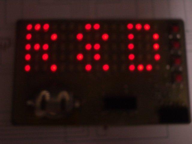
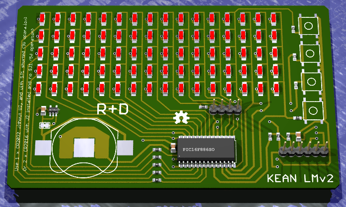
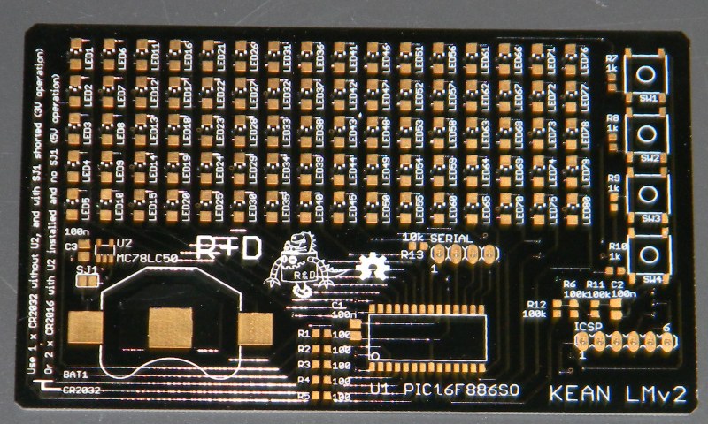
There are 80 small red LED’s arranged in a 5 x 16 matrix, and they are driven by a PIC 16F886, 28 pin SOIC package microcontroller.
Power is supplied by a 3V 2032 coin cell battery, and there are 4 push buttons.
The PIC is programmed via an ICSP connector suitable for the Microchip PICkit 2 programmer.
The first two prototype boards were CNC milled, but they take about 2 hours each, so as they have very few holes to be drilled it will be better to photo etch them.
A big thanks to John Hirsch, who made up some of these boards using his excellent photo etching skills.
As of June 2012, we now have some commercially made PCB's of the V2 design which incorporates a 5V regulator to (hopefully) allow blue or white LED's (Vf>3V), and also an optional serial interface (not yet implemented).
General Info
- The microcontroller used is a PIC (not Atmel or Arduino) because that is what I knew best at the time. I just wanted a quick low cost circuit that could be built in an few hours from scratch.
- The design is a prototype, and yet the first two built are working perfectly. The picture above is one of several sample images that can be selected. The LED's aren't terribly bright, but we might be able to work on improving that.
- The current PCB’s are prototypes – there is no silkscreen or solder mask. It is single sided, with the copper side up.
- You can solder the parts on by hand – it will require fine tweezers, a steady hand, and patience.
- We now have software that is *working* – download HEX files and source below. It is suggested you come up with more ideas and implement them.
- The buttons have no specific function – they can do anything based on your software. The sample code uses the top button to switch images, then 2nd & 3rd to adjust brightness (actually the scan rate), and the bottom button switches to sleep mode (top button to wake up again). This has changed slightly with the v2 software, where the top button selects mode, middle two are up/down, and bottom button selects an action.
- The circuit is designed to allow “ultra low power wake up” via any button under software control, so you can put the PIC into sleep mode without removing the battery, and pressing a specific button will wake it up.
- The power usage is about 5 to 10 mA with the sample code, depending on the pattern and refresh rate. The microcontroller uses about 0.3 mA of that, and only 50 uA when in sleep mode. I believe a good CR2032 Lithium cell is approx 200 mAh, so that should hopefully give about 20 hours of operation, or nearly 6 months in sleep mode! (Actually it turns out that the CR2032 is limited to about 3mA continuous draw, which limits brightness, but means the battery life is somewhat better)
- I plan to add an auto power off timer to the code, to help conserve battery life. (Ooops - I forgot to add this in v2...)
Theory of Operation
Coming later...
Bill of Materials
| Qty | Value | Device | Parts |
| 80 | Red 1206 LED | Stanley BR1102W-1-TR | LED1 - LED80 |
| 5 | 100R | 0603 Resistor | R1 - R5 |
| 4 | 1k | 0603 Resistor | R7 - R10 |
| 3 | 100k | 0603 Resistor | R6, R11, R12 |
| 2 | 100n | 0805 Capacitor | C1, C2 |
| 4 | SMD Button | Jaycar SP0610 | SW1 - SW4 |
| 1 | Battery Retainer | Farnell 908-654 + CR2032 | BAT1 |
| 1 | ICSP connector | 6 way female header | SV1 |
| 1 | PIC16F886-SO | PIC 16F886 Micro | IC1 |
| 1 m | 24 gauge or finer | Jumper wire | (for V1/prototype) |
Circuit Diagram & Files (for V2)


Schematic .PDF
PCB Layout .PDF
Eagle (5.11) .SCH & .BRD
Code from V1 PCB is compatible - but doesn't yet support the serial port
The optional 5V regulator should allow use of higher forward voltage LED's (blue/white) when using 2xCR2016 batteries (untested).
Circuit Diagram & Files (for V1/prototype)
Schematic .PDF
PCB Layout .PDF
Eagle .SCH & .BRD
Reverse PCB image .PDF for photo etching (make sure you print from Acrobat with no scaling)
Hex file v1 .HEX sample code for testing (program into PIC with PICkit 2)
Hex file v2 .HEX for full animated display of several text messages, and Conways Game of Life simulation
Photos (for V1/prototype)
Freshly milled PCB
Jumpers on back
Finished prototype
Tools required
- Soldering iron with a fine tip (most soldering irons suitable for electronics should be fine with care)
- Solder - I don't recommend using lead-free solder unless you have experience with it
- Side cutters / Dikes for trimming jumper wire (for V1/prototype)
- Pliers for bending battery holder legs
- Fine tweezers for placing components
- Magnifying lamp (ideal) or magnifying glass/loupe
Construction steps (for V1/prototype)
- First, examine the board to make sure there are no fine bridges between tracks, especially if the board was milled.
- Check you have all the parts per the BOM – Kean can supply extras if any are missing, or if they get lost during construction. It is very easy to lose the small SMD parts, so be extra careful when handling them. Often they go flying out of sight when you squeeze too hard with the tweezers.
- Start by adding a small blob of solder on each of the top row of LED pads. You can do this on every second row of pads in the matrix. You will then need to carefully place an LED using tweezers, with the green bar towards the top of the board, and "tack" solder it in place using just the solder on the pad. Try to make sure the LED’s are straight and sit flat on the board. Don't use too much heat. Let it cool down if necessary before adjusting. Don’t solder the other side of the LED’s – just do the one side and continue until all 80 LED’s are “tacked” in place.
- Using a good light (and magnifying glass or loupe if you have one) examine the board at different angles to check alignment of all the LED’s, and that there is a good solder joint. The LED's should sit flat against the board, and be reasonable well aligned. Once you solder the other side of the LED it becomes much more difficult to adjust or remove them.
- Add solder to the other side of the LED’s.
- (for V1/prototype) Because the board is single sided, only the 16 columns in the matrix are pre-wired on the PCB (the common cathodes). You need to add 5 (bare) wires to connect the common anodes for the rows. This is soldered in place directly to the 2nd side of the LED, with the wire sitting proud of the circuit board so that it doesn’t short out with the PCB tracks. See the finished prototype photo to get an idea.
- If possible, before adding any more components, use a 10mA power source (e.g. an LED tester, or a 9V battery with a 1k resistor in series) to test the matrix. Apply +ve to each of the 5 row anode connections (coming up at the left) in sequence, and –ve to the 16 column cathodes (coming up from below). As you do this each corresponding LED in the matrix should light up. If not, you might have a bad solder joint, or maybe reversed or overheated the LED.
- Now you should add the SMD capacitors. There are two 100 nF ceramic capacitors, one goes just to the left of the PIC, the other above pin 3 of the programming connector. These are 0805 size (smaller than the 1206 size LED’s but bigger than the 0603 size SMD resistors). Tack solder one side in place, check and adjust alignment, then solder the other side. Be careful not to overheat or stress the capacitors – they can crack easily. The orientation isn’t important – these low value capacitors are non-polarized.
- Now solder on the SMD resistors. They are pretty small, but you can use the same technique. You are likely to need some sort of magnification to read component values and check alignment. There are 3 different resistor values: 3 x 100k go side by side towards the right bottom of the board, 4 x 1k go along side the buttons on the right (3 vertical, one horizontal), and 5 x 100R are placed horizontally at the middle bottom of the board.
- Next is probably the trickiest – you need to solder in the PIC microcontroller. It has 28 pins, which are pretty close together (1.27 mm), so be patient. Pin 1 (marked by a dimple) goes towards the bottom centre of the board. Start by tack soldering one corner, and adjust until all the pins are aligned in both directions. Then tack the other corner and double check. Finally add a little solder to each pad. You should try to avoid solder bridges caused by too much solder, but can always fix them with fine solder wick. Be careful not to overheat the chip, as it will be hard to remove if damaged.
- OK, we are almost done... now the jumper wires. There are 16 holes that need to be drilled (0.7 mm ideally), and 8 parallel wires that need to be placed on the back of the board. The pads are small, so make sure there is a good connection when soldering. These jumpers are needed for the programming connector and push buttons to operate.
- Next the push buttons. The PCB design has the pads slightly too far apart, so you need to be careful when soldering these in place, especially if you have a milled board where you could create a short with the “background” copper.
- Solder the programming connector in place – just bend the legs slightly and solder it in place. You don’t need to drill out these holes.
- Finally the battery holder. You need to add a little bit of insulating tape on the PCB over the tracks in front on this – you can use Kapton (yellow high temperature) tape, electrical tape, or plain sticky tape. Add a thin film of solder to the centre (-ve) pad of the battery, so as to help make a good connection. Then bend the two legs of the battery holder straight out to lay flat on the board, and then solder them on.
- Done!
Testing
You will need a PICkit 2 programmer to load the .HEX file above. There is/was now one available to share in the R&D arsenal of tools & equipment.
Inserting a battery will not light up any LED’s without programming the PIC unfortunately :-(
Source Code
Version 1 code - Simple test program, very limited functionality
Version 2 code - Fully interrupt driven display, hand crafted 5x5 font (actually it is proportional width to fit more on screen), font and scrolling library function, Conways Game of Life simulation, and much tidier code,
The above source files are HI-TIDE projects for the HI-TECH C Compiler. From withing Hi-TIDE you can use File->Import to import the ZIp file directly into your default workspace, and then work on it from there. HI-TIDE does an auto-build on save by default, and the HEX for programming will be under the Release folder under your HI-TIDE workspace.
Resources
- PIC 16F886 data http://www.microchip.com/wwwproducts/Devices.aspx?dDocName=en026562
- PICkit programmer http://www.microchipdirect.com/productsearch.aspx?Keywords=PG164120
- HI-TECH C Compiler for PIC 10/12/16 (free to use in “lite” mode - registration required) http://htsoft.com/products/compilers/piccprocompiler.php
- Stanley BR1102W-1-TR – Red 1206 SMD LED, 647 nm, Vf=1.7V, 33mcd @ 20mA http://parts.digikey.com/1/parts/683419-led-red-clear-1206-smd-br1102w-tr.html
License
This project is licensed under the
Creative Commons Attribution ShareAlike license

Other OSHW
Home
© 2009-2018 Kean Electronics Pty Ltd, ABN 73 627 091 196
Last updated: 2nd July 2018


